The most common of all LCD technologies is TN (twisted nematic) technology. A TN display consists of several TN cells that function like a kind of water tap in which light flows instead of w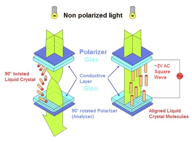 ater.
ater.
A TN cell consists of two linear polarisation filters that are rotated 90° to each other. Between the filters are two transparent electrodes (a pixel electrode and a common back electrode). These usually consist of a glass plate with an ITO (indium tin oxide) layer on it. On the ITO layer is the orientation layer, which is arranged at 90° to each other like the polarising filters. In between are the elongated liquid crystals.
The crystals are arranged along the two orientation layers. The name “twisted nematic” is based on the twisted arrangement of the crystals. When unpolarised light from the backlight hits the first polarising filter, it becomes linearly polarised. The light passes through the electrode and hits the liquid crystals. The polarisation plane of the light is rotated 90° by the arrangement of the crystals. In this way, the light can also pass through the second polarisation filter.
This makes the LCD cell transparent to light. If a voltage is now applied to both electrodes, an electric field is generated between the two opposing electrodes. This field causes the crystals to no longer arrange themselves along the orientation layer, but along the electric field lines. If the linearly polarised light now hits the liquid crystals, the polarisation plane is no longer twisted.
If the unchanged light hits the second polarisation filter, it is absorbed because the polarisation plane is no longer the same. The LCD cell is not transparent to light. The cell is therefore transparent when no voltage is applied and non-transparent when voltage is applied (normal white mode). In between, the luminous flux is continuously adjustable with the voltage.
The most common of all LCD technologies is TN (twisted nematic) technology. A TN display consists of several TN cells that function like a kind of water tap in which light flows instead of water.
A TN cell consists of two linear polarisation filters that are rotated 90° to each other. Between the filters are two transparent electrodes (a pixel electrode and a common back electrode). These usually consist of a glass plate with an ITO (indium tin oxide) layer on it. On the ITO layer is the orientation layer, which is arranged at 90° to each other like the polarising filters. In between are the elongated liquid crystals.
The crystals are arranged along the two orientation layers. The name “twisted nematic” is based on the twisted arrangement of the crystals. When unpolarised light from the backlight hits the first polarising filter, it becomes linearly polarised. The light passes through the electrode and hits the liquid crystals. The polarisation plane of the light is rotated 90° by the arrangement of the crystals. In this way, the light can also pass through the second polarisation filter.
This makes the LCD cell transparent to light. If a voltage is now applied to both electrodes, an electric field is generated between the two opposing electrodes. This field causes the crystals to no longer arrange themselves along the orientation layer, but along the electric field lines. If the linearly polarised light now hits the liquid crystals, the polarisation plane is no longer twisted.
If the unchanged light hits the second polarisation filter, it is absorbed because the polarisation plane is no longer the same. The LCD cell is not transparent to light. The cell is therefore transparent when no voltage is applied and non-transparent when voltage is applied (normal white mode). In between, the luminous flux is continuously adjustable with the voltage.