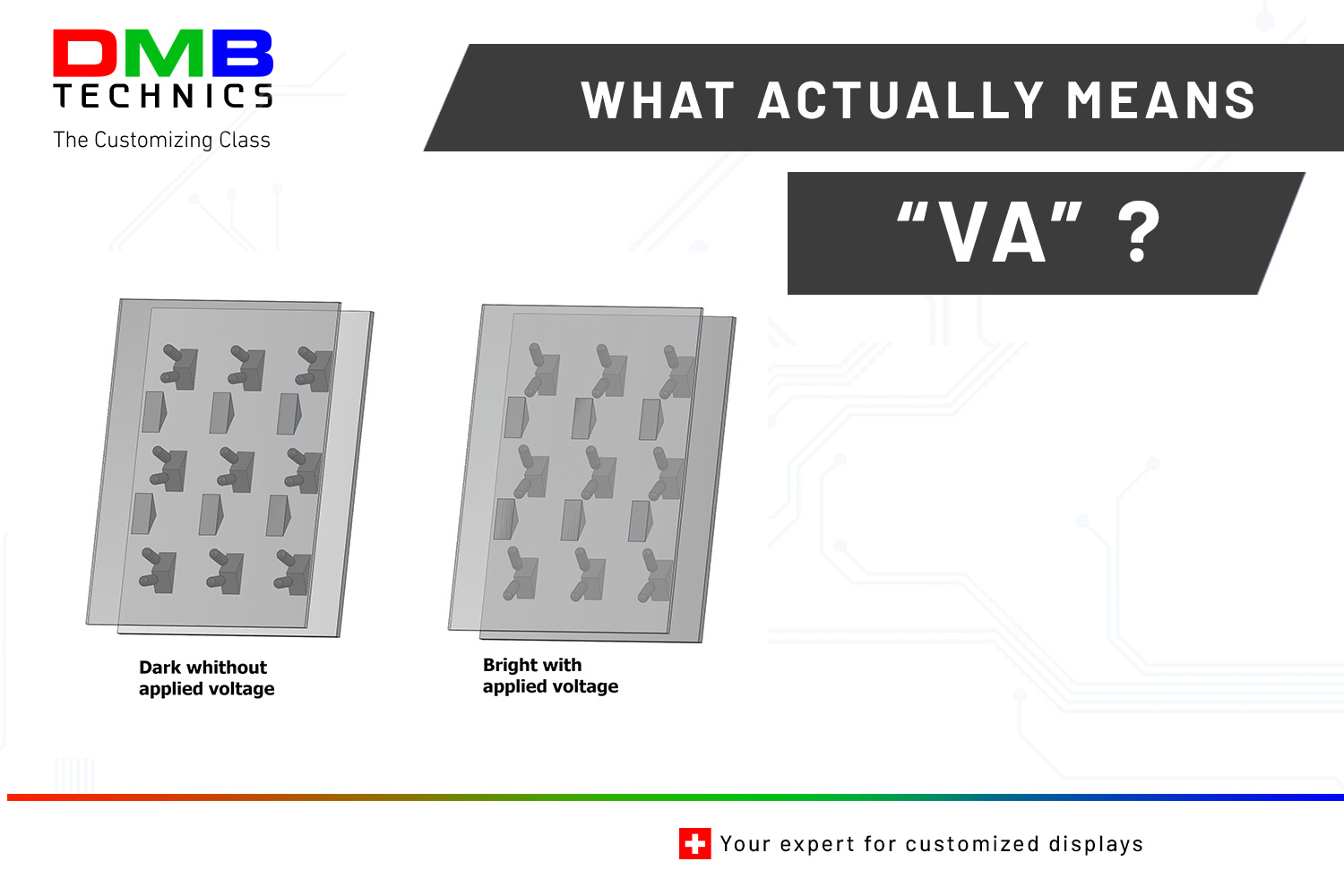
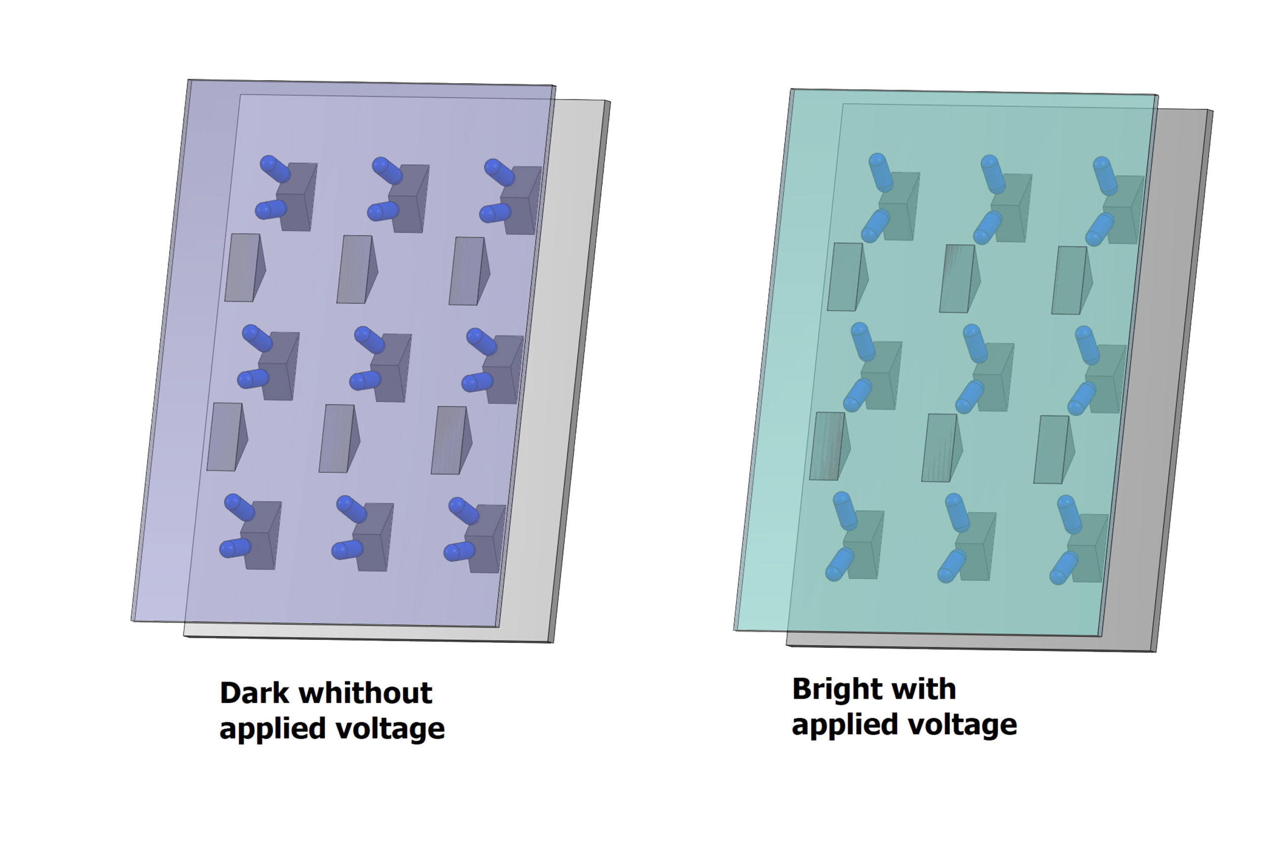
Between the filters are two transparent electrodes (a pixel electrode and a common counter electrode). These usually consist of a glass plate with an ITO layer (indium tin oxide) applied. On top of this is the orientation layer. The elongated liquid crystals are embedded in between. The crystals arrange themselves along the two orientation layers vertically to the surface. This is why they are also called “vertical aligement”. When unpolarised light from the backlight falls on the first polarising filter, it becomes linearly polarised.
The light passes through the pixel electrode and hits the liquid crystals. The polarisation plane of the light is not changed by the arrangement of the crystals. Therefore, the light cannot pass through the second polarisation filter because the polarisation plane is not the same. This means that the LCD cell is not transparent to light and appears very dark. If a voltage is now applied to both electrodes, an electric field is created between them. This field causes the crystals to no longer arrange themselves along the orientation layer, but along the electric field lines. These flip over parallel to the surface. If the linearly polarised light now hits the liquid crystals, the polarisation plane is rotated by 90° and can pass through the second polarisation filter. The LCD cell is transparent to light. The cell is therefore non-transparent (black) when no voltage is applied and transparent (white) when a voltage is applied.
This is called “normal black mode”. In between, the luminous flux is continuously adjustable with the voltage. The advantage of this technique is the higher contrast value achieved by the vertical arrangement. In addition, the viewing angle stability from the side view is significantly improved. A disadvantage is a longer reaction time. This can lead to streaking. In addition, this technology consumes slightly more power compared to a TN panel and is more expensive to produce.